Working Group 4 of the Portuguese Commission of Tunnels and Underground Space decided to present the webinar “BIM for GeoSciences” organized by Geovita AS (Geotechnical and Rock Mechanics engineering consultants in Norway) and NGI (Geotechnical Institute of Norway). This webinar is about BIM modeling of underground structures and ground conditions and is divided into several parts.
The first edition of this webinar, previously presented by the CPT GT4, can be viewed and consulted through the following links:
Sinopse Part 1 PT (8 min read): Link https://cpt.spgeotecnia.pt/page/news/36
Webinar Part 1 EN (57:42): https://www.youtube.com/watch?v=pmu5iUVCdnE
The second part addresses the modeling of geological conditions in infrastructure projects and the use of parametric modeling to optimize the design of support elements in tunnels and rock masses.
Sinopse Part 2 PT (9 min read)
Webinar Part 2 EN (54:52): https://www.youtube.com/watch?v=Xvwg4_F6azY
#webinar #bim #geology #parametric_modeling #tunnels #support_elements
Part 2
Three-dimensional modeling of geological conditions
The three-dimensional modeling of the land surface and the subsoil geology becomes fundamental in the context of underground works designed using BIM technology.
In the design phase, firstly, the information present in the geological maps and available boreholes is used, and then the quality of the geological model can be evaluated and the need to carry out additional boreholes verified, being the surface of the rock mass, or any other geological formation, defined using Leapfrog Works software. In relation to the surface of the ground, a cloud of points collected by ‘laser scanning’ can be used to define it.
Later in the construction phase, the geological model can be adjusted and updated based on the information collected at the excavation front, either through visual inspection, performing horizontal boreholes or even using methods that use the measurement of certain quantities during drilling.
The great advantage of defining the geological model a priori is the possibility that, having a dynamic character, at any stage of the project it can be adjusted through the introduction of new available information. The model makes it possible to easily define the most relevant views for the work in question, such as the longitudinal profile along the tunnel path and equidistant cross-sections. Subsequently, the introduction of the structural project in the geological model allows reassessing and eventually optimizing the tunnel layout, evaluating, for example, the estimated volumes of each lithological formation to be excavated.
The webinar presents, as an example, the creation of a geological model using Leapfrog Works software.
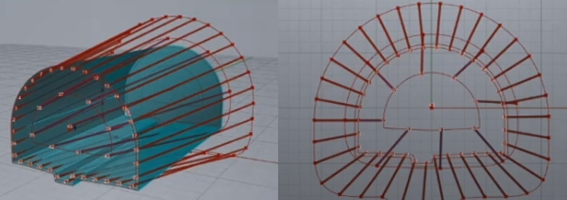
Rock mass tunnels: design using parametric modeling
The parametric modeling of primary support systems in rock tunnels allows a better interface in the definition and updating of the dimensioning of the elements, being the parametric character decisive in the definition of the variable attributes of each element.
To model the primary support of tunnels in rocky massifs, the Rhinoceros software can be used, using the Grasshopper visual programming environment, which allows to parametrically define each of the structural elements and later adjust the value of their attributes and see, in parallel, the graphic effect of these changes in the Rhinoceros software. The defined solution can be exported in several formats and, in particular, the geometric magnitudes of the elements can be exported in CSV format.
As an example, a solution is presented where the primary support is constituted by pipe umbrella systems, with its initial geometry defined by changing the previously established attributes. Subsequently, geological information is added, namely a volume corresponding to the soil mass and the respective fracturing. Thus, through the use of the Galapagos add-on, the so-called evolutionary computation is applied which, after the introduction of the appropriate variables, and evaluation and computation of a pre-established number of combinations, converges to an optimal solution. In this particular case, the length and slope of the pipes is iteratively adjusted to suit the fracture structure of the rock mass. After defining the primary support system, it can be recorded and applied to the global model of the tunnel in the length for which the fracture model of the rock mass was considered representative.
The parametric modeling considering a primary support system composed of nailings is also presented. The solution definition is studied for different excavation classes and defined in XLS format. Subsequently, this information is used in conjunction with the rock mass classification (in terms of the RQD parameter along the tunnel path), to automatically define the location of the support elements with the geometric characteristics adjusted to the local geological scenario.
Rock slopes: from remote monitoring to the design of support elements
The three-dimensional modeling of rock mass outcrops achieved through aerial means of collecting information, particularly in slope areas, allows estimating fracture spacings, better estimating the geometry of transverse profiles for global stability assessment and more easily identifying potentially unstable blocks.
The two main methods of remotely gathering information are Photogrammetry and LIDAR technology, typically through the use of a laser. Both methods allow obtaining the point cloud of the area under analysis.
Photogrammetry is a method that requires a greater computational effort due to the need to superimpose multiple images and establish common points and later scale and georeference them. It is estimated that for a good quality of information, a minimum of 80% and 60% of horizontal and vertical image overlap, respectively, is required.
Despite the greater need for processing, this method is advantageous over the LIDAR method as it is suitable for large areas, minimizes blind spots and is more economical. However, it can only be used in illuminated environments and does not allow crossing vegetation elements.
Three-dimensional modeling of the rock mass and stabilization elements using Rhinoceros/Grasshopper software allows for a better visual understanding, an interactively optimized dimensioning and a better flow of information. The information regarding the supporting structural elements can be easily exported to a CSV file that will include all the geometric information necessary for the execution of the elements.
It is also possible to establish a rupture surface in the three-dimensional model and, by defining a script, automatically adjust the length of the support elements in order to exceed that surface.
BIM Webinars for Geosciences Part 3 and Part 4
The CPT GT4 will soon present synopses for the remaining editions of this webinar. These editions can be viewed via the following links:
Webinar Part 3 EN (48:37): https://www.youtube.com/watch?v=5frwiM9Gd4s
Webinar Part 4 EN (55:01): https://www.youtube.com/watch?v=k_WdtkEWuFk